| Number | name | Reference dimensions | Remarks |
| 1 | Single stage cylindrical gear reducer(Customized by Tsinghua University) | 220*230*170(Length×Width×Height) | Equipped with: exploded view of parts drawing |
| 2 | A-type gear pump(lying) | 150×180×150(Length×Width×Height) | Equipped with: exploded view of parts drawing |
| 3 | B-type gear pump(Standing) | 220×160×180(Length×Width×Height) | Equipped with: exploded view of parts drawing |
| 4 | C-type gear pump(Standing) | 150×160×140(Length×Width×Height) | Equipped with: exploded view of parts drawing |
| 5 | E-type gear pump(Standing) | 190×130×180(Length×Width×Height) | Tianjin pump |
| 6 | K-type gear pump | 200×150×180(Length×Width×Height) | Equipped with: exploded view of parts drawing |
| 7 | R-type gear pump | 170×110×115(Length×Width×Height) | Southeast University |
| 8 | T-type gear pump | 210×160×130(Length×Width×Height) | Taiyuan Institute of Technology |
| 9 | Diesel engine oil pump | 200×160×180(Length×Width×Height) | - |
| 10 | Gear oil pump(05)vertical | 200×160×180(Length×Width×Height) | Equipped with: exploded view of parts drawing |
| 11 | Gear oil pump(07)vertical | 160×140×140(Length×Width×Height) | Shenyang Institute of Aeronautics and Astronautics |
| 12 | Cycloidal rotor oil pump | 180×150×150(Length×Width×Height) | - |
| 13 | Lubricating oil pump | 130×150×100(Length×Width×Height) | Equipped with: exploded view of parts drawing |
| 14 | Milling cutter head | 280×220×150(Length×Width×Height) | Equipped with: exploded view of parts drawing |
| 15 | Machine vice | 250×180×140(Length×Width×Height) | Equipped with: exploded view of parts drawing |
| 16 | Flat nose pliers | 220×140×80(Length×Width×Height) | Equipped with: exploded view of parts drawing |
| 17 | Integrated bearing seat | 150×100×80(Length×Width×Height) | - |
| 18 | Split sliding bearing seat | 180×160×100(Length×Width×Height) | Equipped with: exploded view of parts drawing |
| 19 | Automatic locking cock | 220×100×150(Length×Width×Height) | - |
| 20 | Drilling die | 150×100(long × wide) | - |
| 21 | Micro motion mechanism | 240×100×140(Length×Width×Height) | Equipped with: exploded view of parts drawing |
| 22 | Jack | 150×80×100(Length×Width×Height) | - |
| 23 | Assembly diagram of movable wheel frame | 180×100×120(Length×Width×Height) | - |
| 24 | safety valve | 200×130×120(Length×Width×Height) | - |
| 25 | ball valve | 80×90×160(Length×Width×Height) | - |
| 26 | ball valve | 150×180×260(Length×Width×Height) | Equipped with: exploded view of parts drawing |
| 27 | Quick valve | 200×180×190(Length×Width×Height) | Equipped with: exploded view of parts drawing |
| 28 | Plunger pump(horizontal) | 180×120×120(Length×Width×Height) | - |
| 29 | Plunger pump(Vertical 1) | 190×100×100(Length×Width×Height) | Equipped with: exploded view of parts drawing |
| 30 | Plunger pump(Vertical 2) | 200×120×220(Length×Width×Height) | Equipped with: exploded view of parts drawing |
| 31 | Air release valve | 100×50×70(Length×Width×Height) | - |
| 32 | Valve assembly diagram | 120×90×150(Length×Width×Height) | - |
| 33 | valve body | 100×70×100(Length×Width×Height) | - |
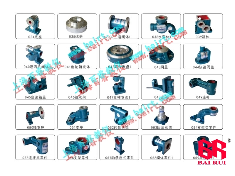
| 34 | base | 92×60×126(Length×Width×Height) | - |
| 35 | End cap | 90(diameter)×37 | - |
| 36 | Fork shift | 100×66(long × wide) | - |
| 37 | Three-way valve body | 80×80×95(Length×Width×Height) | - |
| 38 | Water pump body | 160×75×98(Length×Width×Height) | - |
| 39 | Box body | 108×108×98(Length×Width×Height) | - |
| 40 | Sprayer valve body | 120×60×140(Length×Width×Height) | - |
| 41 | Gearbox housing | 128×88×60(Length×Width×Height) | - |
| 42 | Clutch disc | 140×140×40(Length×Width×Height) | - |
| 43 | Valve cover | 120×120×60(Length×Width×Height) | - |
| 44 | Quick valve cover | 100×80×100(Length×Width×Height) | - |
| 45 | Transmission cover | 150×150×52(Length×Width×Height) | - |
| 46 | Bearing frame | 140×50×110(Length×Width×Height) | - |
| 47 | Column bracket | 105×90×125(Length×Width×Height) | - |
| 48 | support | 85×85×130(Length×Width×Height) | - |
| 49 | connecting rod | 75×64×144(Length×Width×Height) | - |
| 50 | Shaft support | 125×85×65(Length×Width×Height) | - |
| 51 | Support | 142×110×135(Length×Width×Height) | - |
| 52 | Grinding wheel head frame | 142×192×120(Length×Width×Height) | - |
| 53 | Return valve cover | 65×65×90(Length×Width×Height) | - |
| 54 | Bracket parts | 60×120×60(Length×Width×Height) | - |
| 55 | Connecting rod parts | 140×80×60(Length×Width×Height) | - |
| 56 | Support components | 60×120×60(Length×Width×Height) | - |
| 57 | Bearing seat type parts | 80×60×120(Length×Width×Height) | - |
| 58 | Valve body parts | 80×80×130(Length×Width×Height) | - |
| 59 | Base parts | 90×90×60(Length×Width×Height) | - |
| 60 | Complex parts | 80×90×120(Length×Width×Height) | - |
| 61 | Seat frame | 80×80×130(Length×Width×Height) | - |
| 62 | Tailstock seat | 100×85×125(Length×Width×Height) | - |
| 63 | Deformable connecting rod | 100×60×70(Length×Width×Height) | - |
| 64 | valve seat | 80×80×110(Length×Width×Height) | - |
| 65 | disc | 125×70(long × wide) | - |
| 66 | base | 100×80×60(Length×Width×Height) | - |
| 67 | Shaft seat | 120×90×50(Length×Width×Height) | - |
| 68 | valve body | 80×100×70(Length×Width×Height) | - |
| 69 | base | 80×100×40(Length×Width×Height) | - |
| 70 | valve body | 80×100×100(Length×Width×Height) | - |
| 71 | Axonometric frame | 80×120×70(Length×Width×Height) | - |
| 72 | Valve body cover | 85×85×90(Length×Width×Height) | - |
| 73 | Shaft sleeve | 150×70(At the maximum diameter) | - |
| 74 | Chain connection | 150×120(long × wide) | - |
| 75 | South axis(1) | 300×42(Length×Width×Height) | - |
| 76 | South axis(2 | 300×45(At the maximum diameter) | - |
| 77 | South axis(3 | 300×32(At the maximum diameter) | - |
| 78 | South axis(4) | 300×45(At the maximum diameter) | - |
| 79 | South axis(5) | 300×45(At the maximum diameter) | - |
| 80 | Shangong axis(1) | 300×38(At the maximum diameter) | - |
| - | Surveying model | 10 piece set | - |






 Return to homepage
 Immediately call for consultation
 About Us
 Immediately consult online